A recent evaluation by a marine electrician to determine whether my boat was over-zinced was followed by a recommendation to update the bonding system of Skiron. The vessel was bonded according to European standards when constructed in Sweden and it was suggested that we bring it to US standards. I must admit, however, that I am a novice with a little understanding of marine electronics. There comes a point in time when you have to trust those who do something for a living and simply take their recommendations.
Here is a nice link that describes, fairly well, the bonding system of a vessel.
https://www.cruisingworld.com/avoid-corrosion-with-bonding-system/
The first step in the process was to remove personal belongings, tools, spares, cushions, etc. from the forward half of the boat to the aft portions. Next, I removed all of the floorboards to expose the bilge.

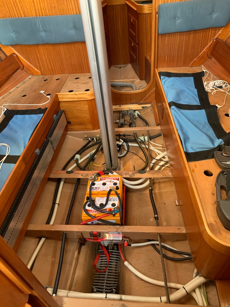
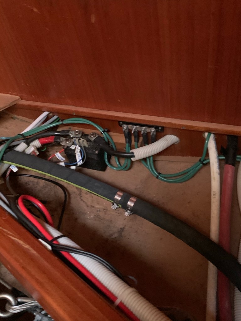
A lot of things are being accomplished during this first phase. A few parts have been upgraded. Bonding buses have been put in place.
After a few days, the forward half of the boat was appropriately bonded, battery cables were changed and a few other things were accomplished. Then, I moved everything from the aft part of the boat back to its usual locations in the forward part and moved all of the things in the rear of the boat to the forward compartments, thus exposing the reminders of the innards of boat to continue the process of bonding and an ongoing evaluation of the electrical system on the vessel.
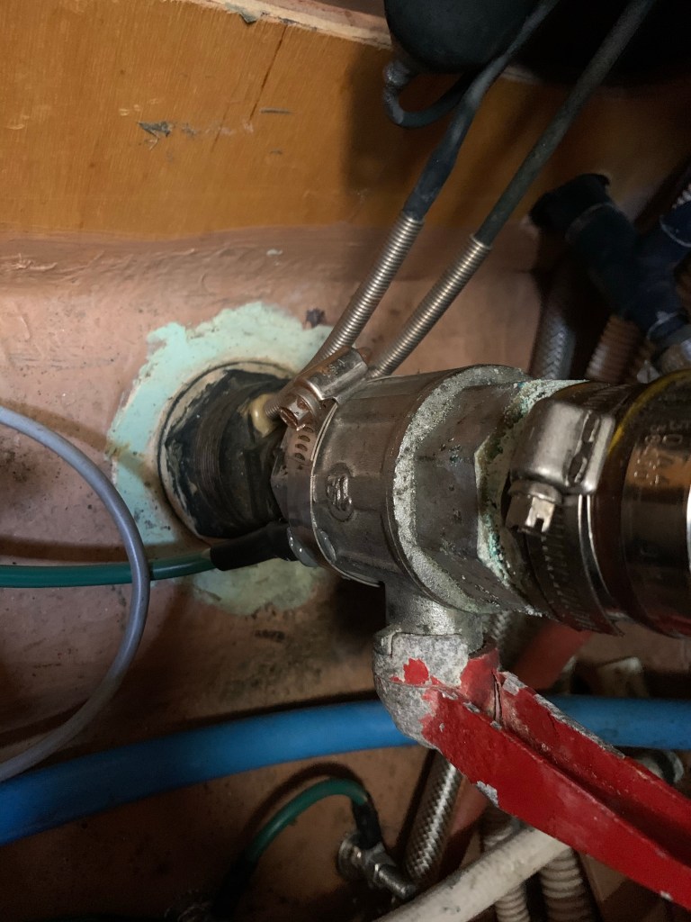
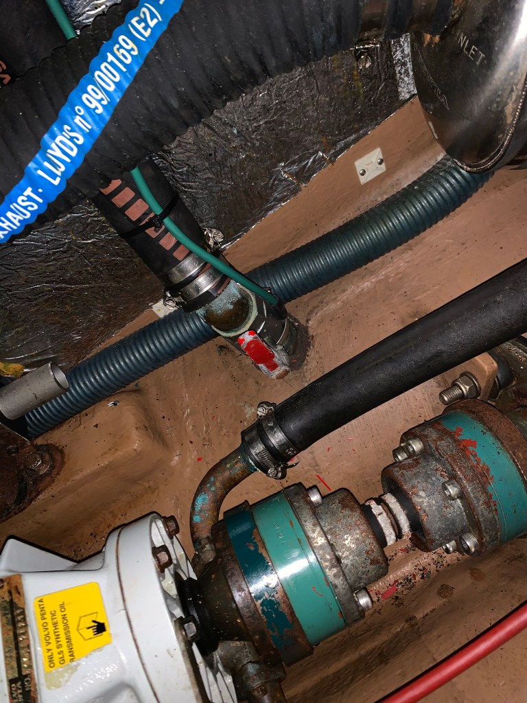
I’m impressed with the agility required to bond some parts including the through hulls located in the engine compartment. Also, locating a bus bar in same must have been next to impossible. The apprentice marine electrician, when I asked how she was able to accomplish those tasks replied, simply, “boat yoga.”


I learned more by asking Malcolm Morgan, a noted and well respected Bay Area marine electrician and sailor I have working on the vessel who had this to say…..
Most European vessels are built without any form of bonding system. This is the subject of great controversy but ultimately they rely on RCD circuit breakers on the incoming shore power system (similar to our GFI breakers used in the USA) to prevent electrocution risks to the crew, or people in the water around the vessel. But this does nothing to protect the underwater fittings on the vessel from corrosion. Corroded seacocks and prop shafts are common.
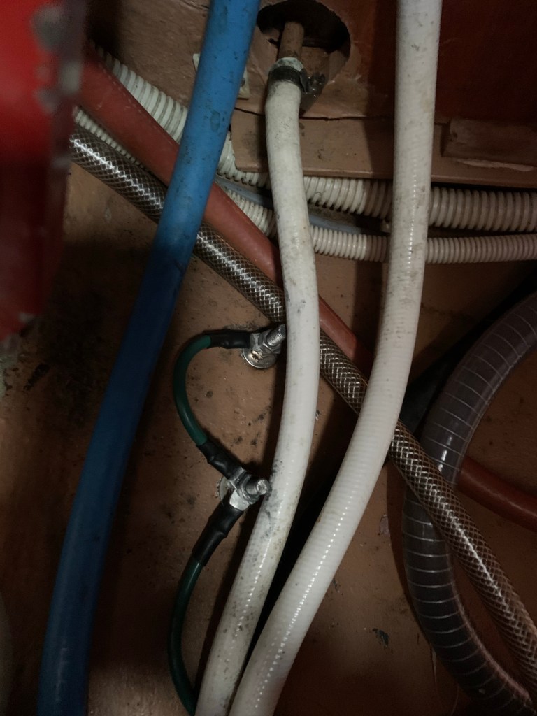
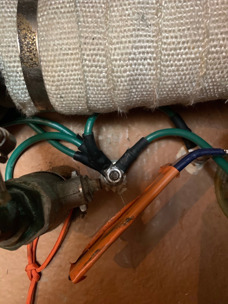
Somewhere in the past, several underwater fittings were added to the hull of Skiron for a SSB radio, and/or to attempt to reduce corrosion on some of the underwater fittings. But in this case there was an odd collection of different wires sizes, and most of the connections were made with bare copper wire, and plastic cable ties holding the wires onto the metal thru-hull fittings. Many of the underwater fittings were not included in this system, and the ones that were connected were all at slightly differing voltages (potentials).
The purpose of the bonding system is two-fold:
1. It is intended to be a robust, low resistance connection to all of the underwater fittings, so they are all at the same voltage, or potential. Then this bonding system connects to the main zinc plate on the hull, and to a set of heavy duty shaft contacts (shaft brushes) that connect the spinning prop shaft, and the moving rudder post, to all of the other underwater fittings, AND the sacrificial zinc plate, so that everything is held at the safe protected potential for those types of metals. In the case of Skiron, all of the underwater metals are in the same protected range, or group. Group 1 metals are brass, bronze, stainless steel, lead, etc. The target safe voltage for these metals is 50mV DC to 550mV DC. as long as the bonding connections are intact, and the sacrificial zinc anode is maintained, almost of the corrosion stops and the metals are protected.
With the old system, the voltages were different on almost every fitting due to the weak or missing bonding connections.
2. The other main function of the bonding system, is for shock prevention in the event of an AC electrical fault in an appliance or power tool. When finished, the central point of the bonding system will also be connected to AC safety ground system, and DC negative system, so the voltage on all of the AC appliances, all of the underwater fittings, and the engine block, are all held at the exact same voltage, which is close to zero volts. If there is ever a fault in an appliance, instead of just ‘electrifying’ the case of the appliance, the safety ground system, and bonding system keep the voltage on all the connected metal parts of the boat at cose to zero volts, which will trip the circuit breaker, and prevent anyone onboard from getting a shock.
Also if there was ever a fault in a DC component or wire, that shorted or arced to an underwater metallic fitting, the bonding system prevents the Dc fault from ‘energizing’ the fitting, which could cause it to quickly dissolve away due to stray DC current.
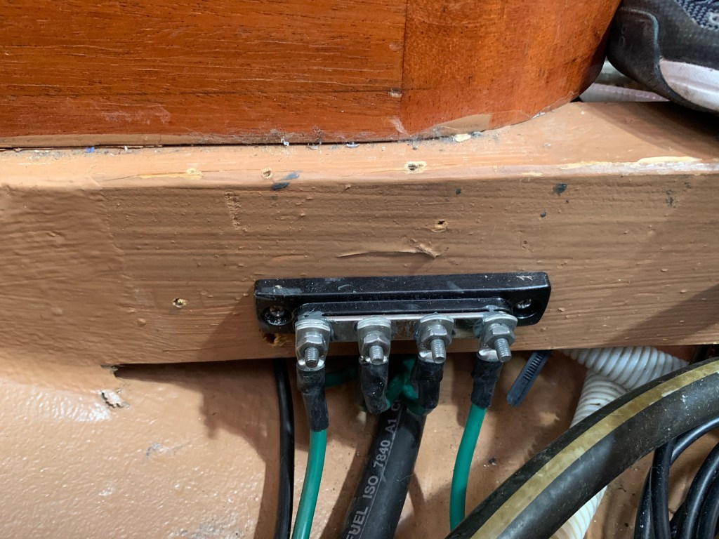
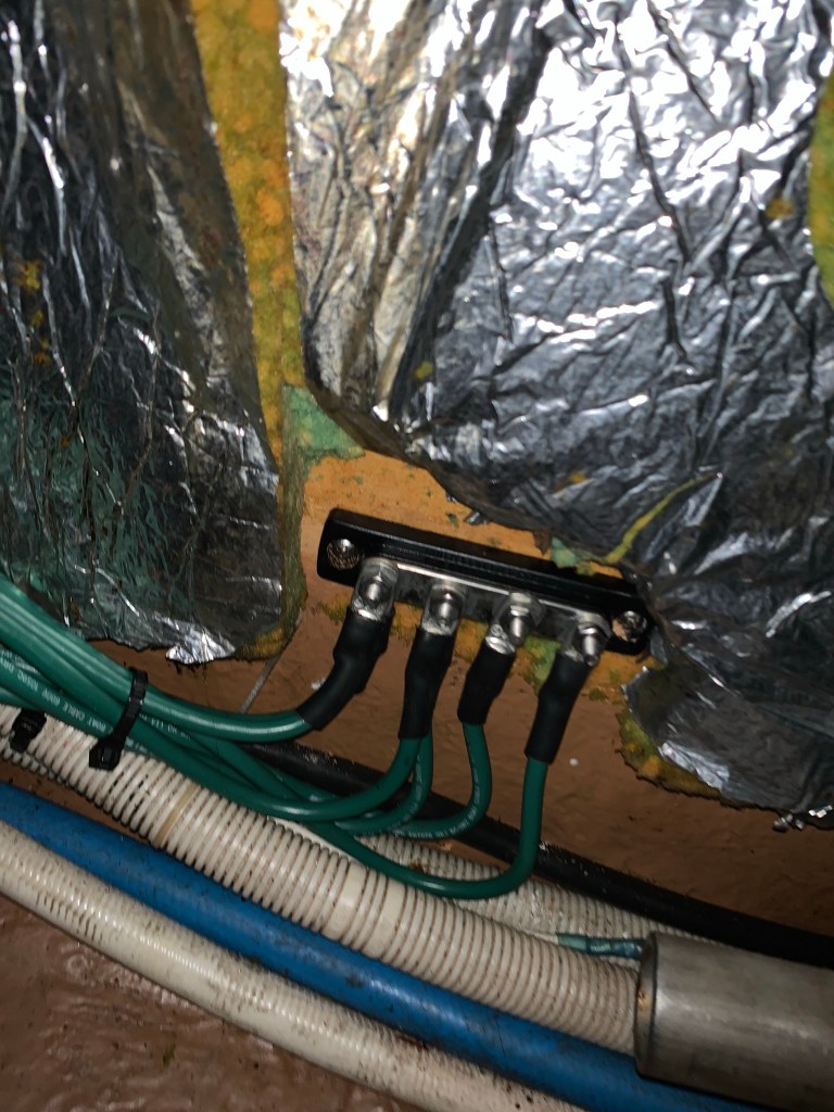
To complete the bonding system, we used approximately 130ft of #8AWG green wire. The wire is tinned for corrosion protection, and the end fitting lugs are ‘closed end’ style that seals the ends of the wire. The lugs are double-crimped onto the wire, then sealed with waterproof heat shrink tubing. Each connection is made using bolts or stainless steel hose clamps, and every fitting is wire-wheeled to bright, clean metal before assembly. A special conductive paste is used to ensure good contact, and then after everything is finished, we apply 2 coats of waterproof electrical sealer spray. All of this is very labor intensive; there are approximately 50 terminations, each one takes over an hour from start to finish, including the time to pull the wires to all of the various locations.
One of the challenges in doing these bonding systems on modern boats, is there can be up to 5 different ‘grounding’ sytems:
1. AC Safety Ground – normally carries NO current, except during a fault condition.
2. DC Negative – this is the return current path for all 12V DC devices on the boat.
3. Cathodic Protection Bonding System – this carries very low voltage and current, JUST for the purposes of corrosion protection, and in an emergency, it carries ‘fault’ current, instead of that current going through a victim or into the water.
4. Lightning Protection System – if installed (Skiron currently does not have a LPS) this is a large cable down the mast, and a lightning rod or ‘air terminal’ on top of the mast, and carefully placed copper plate or strip outside the hull, plus surge arrestors in the mast cables.
5. SSB radio ground plane – usually this is big strips or sheets of copper foil or screen connecting all of the INTERNAL metallic parts together, to act as a radio counterpoise. Skiron had parts of this system but much of it is being removed and the radio will be replaced by a SatPhone.
All 5 of these systems need to be complete, discreet systems, yet they also all need to be carefully connected together to work properly. There seem to be experts on each of these systems separately, but very few people seem to know how to integrate all of them together to work properly.
When finished, the system on Skiron will have 4 separate bus bars devoted to the underwater bonding system, each connected together to form a complete zone of protection for the underwater fittings. On some boats, certain items have to be isolated from each other, and protected separately. this is particularly important on boats with aluminum saildrives, or aluminum rudder posts. Since all of the underwater fittings on Skiron are in the same Group 1, they can be connected and protected together.
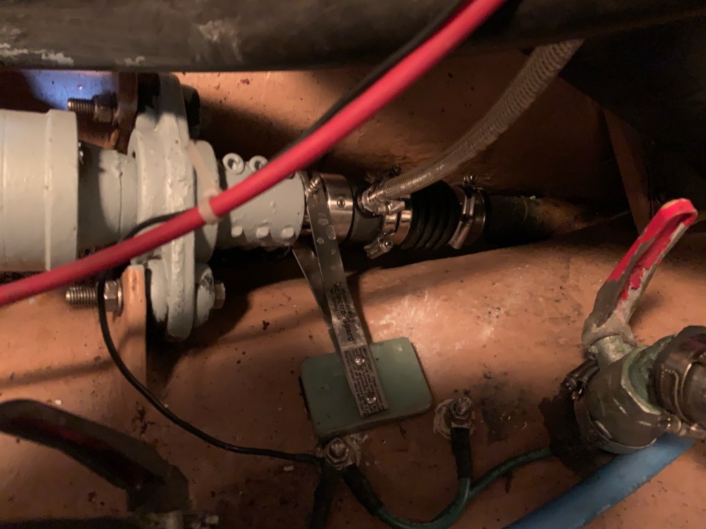
The last step in the process of completing the bonding was to add new shaft brushes and supports to the propeller shaft.
Malcolm visited the boat once the shaft brushes were in place. Here’s what he had to say…..
We went back and tested the bonding system today post-haulout, and the results are all nearly perfect. The target range is 50 to 550mV DC for your types of metals:
mast / mast base 70mVkeel bolts 71mVmid section bonding bus 72mVshaft / shaft brush 73mVengine room bonding bus 73mVrudder post 73mVcopper SSB / aft two studs 73mVaft section bonding bus 73mV
So at these voltages we are well within the safe range for Group 1 metals (copper, brass, bronze, stainless, etc) and you are not overprotected.
We also checked the shore power for AC leak current with shore charger on and off, and it was less than 4mA.
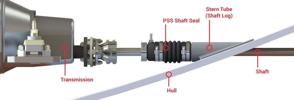
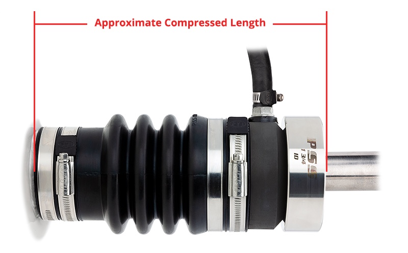
During the process of applying the shaft brushes, it was noted the accordion boot of the PSS shaft seal was worn, twisted, and twisted more when the drive shaft was rocked back and forth. Thus, to avoid a catastrophic fail with an ingress of water that would be difficult to manage, the vessel was hauled out and the assembly was replaced.

I solved this issue on my Hanse by replacing all metal through hulls and seacocks with non metallic Trudesign fittings. All that remains is the saildrive and rudder post which each have there own zincs.
LikeLike